Cut Out Measurement for E120 Radar
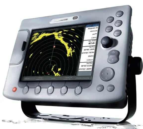
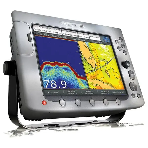
The E120 radar is a well-known multifunction display unit that is utilized in marine navigation systems. This powerful gadget from Raymarine combines GPS, radar, sonar, and other vital marine systems into a single interface. The right cut-out measurement is essential for ensuring a precise, secure, and dependable installation of this radar on a yacht, fishing boat, or other marine vessel. We will go over everything you need to know about the cut out measurement for the E120 radar in this blog post, including how to prepare, how to measure, what tools are needed, and important installation advice.
If you are a boat owner, marine technician, or installer who wants to improve the E120 radar’s performance and appearance, cut out measurement for e120 radar guide will be especially helpful.
How to Use the Cut Out Measurement for E120 Radar: An Overview

It is essential to have a fundamental understanding of the features and functions of the E120 radar prior to delving into the specifics of the cut-out measurement. The E120 is part of Raymarine’s E-Series multifunction displays (MFDs), which combine various communication and navigational tools into a single system. Chart plotting, GPS navigation, radar integration, sonar for fishing, and AIS (Automatic Identification System) for vessel tracking are all features provided by these devices to mariners.
The E120 radar model is made to work with a variety of Raymarine radar antennas and transducers, making it possible for boaters to stay aware of their surroundings in a variety of weather and lighting conditions. The E120’s 12.1-inch display makes it suitable for vessels ranging in size from medium to large.
When installing the E120 radar, one of the most important things to make sure that the cutouts on the console or dashboard are the right size. This will allow the unit to fit perfectly and work properly without any gaps or misalignments.
Precision is Crucial
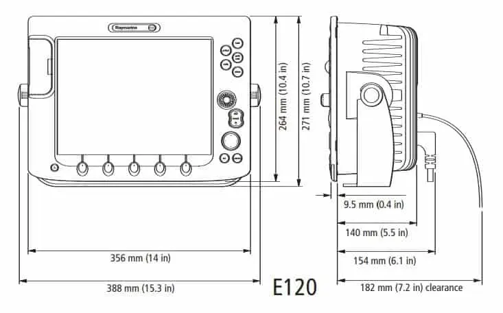
When installing any electronic device, especially in the harsh marine environment. Accurate cut-out measurements are essential. The dimensions of the hole or slot that needs to be cut into the console, dash, or mounting panel where the E120 radar will be installed are referred to as the cut-out measurement. The cutout prevents damage from excessive movement or water ingress and ensures that the radar fits flush with the panel.
An exact cut-out offers a few advantages:
• Structural Reliability: reduces stress and wear on the device and its components.
• Imperviousness: ensures that the unit is properly sealed to prevent electronics from being damaged by water.
• Visual Appeal: The installation looks professional thanks to the neat cutout.
• Access Ease: Access to the cables and connections in the rear for maintenance is made easier with the right fit.
A cutout that is not done well can have a loose or uneven fit, which can cause problems with operation or even cause the radar system to fail. Therefore, it is essential to adhere to the cut-out measurement instructions provided by the manufacturer.
Tools and Supplies Required
Before beginning the cut-out process, it is necessary to gather the necessary tools and supplies. It will save time and ensure a more precise job if everything is on hand. The following is a list of things you’ll need:
• Ruler or measuring tape: to guarantee accurate measurements.
• Marking instrument or pencil: to trace the cut-out’s outline.
• Oscillating multi-tool or jigsaw: for cutting the panel cleanly.
• Bits and drill: to initiate the cut and possibly secure the radar.
• Sandpaper or a file: to smooth out the cut edges.
• Template, if one exists: Installation templates for precise cutting are frequently provided by Raymarine.
Additionally, to ensure that the E120 radar is properly sealed after installation to prevent water ingress, you may require silicone or marine-grade sealant.
Manufacturer’s cut out measurement for E120 Radar
The following are the typical cut out measurement for E120 radar, according to the manufacturer’s cut-out specifications:
•Width: 289 millimeters (11.38 inches)
• Depth: 209 mm (8.23 inches) 88 mm, or 3.46 inches, is the size of the hole you’ll need to cut in the panel to ensure a snug fit. Keep in mind that these measurements are only applicable to the radar display of the E120 and do not take into account the additional space needed for ventilation or wiring.
The exact cut-out dimensions should always be found in the specific installation manual because they may change slightly based on the model or any Raymarine updates.
Guide for Measuring and Cutting in Step-by-Step Form

Step 1: Choose the Installation Location
The location where the radar will be mounted is the first step in the installation process. The E120 radar should ideally be mounted in a spot that is protected from excessive exposure to the elements and easily visible from the helm. For navigational instruments, many boats have dedicated mounting panels; however, if you are retrofitting, check to see that there is enough room for the radar and its wiring connections.
Step 2: Mark the Cut-Out Area
After selecting the location, draw an outline of the cut-out area on the panel with a pencil or marker in accordance with the suggested dimensions. Tape the paper template that Raymarine provided with the E120 radar to the panel and trace the outline, if any.
Before cutting, double-check your measurements because errors at this stage can cause unnecessary problems.
Step 3: Starter Holes
Drill starter holes in the corners of the marked area before using a jigsaw. You can insert the jigsaw blade through these holes and guarantee precise cutting along the lines you’ve drawn.
Step 4: To Cut the Panel
Use a jigsaw or oscillating multi-tool to carefully follow the traced outline. Because jagged edges can disrupt the fit and finish of the installation, take your time to ensure that the cuts are clean and straight. Smooth the cutout’s edges with a file or sandpaper if needed.
Step 5: Test Fit the Radar
Put the E120 radar through its paces by inserting it into the slot after the cutout has been completed. The device ought to fit comfortably without being pushed in. Trim or sand the edges carefully to ensure a perfect fit if adjustments are required.
Securing the E120 Radar After obtaining the ideal fit, the E120 radar must be secured to the panel as the final step. For most installations, the unit will need to be held in place with screws or bolts. To prevent corrosion, use marine-grade fasteners or stainless steel.
Before securing the radar to the panel, apply a thin layer of marine-grade silicone or sealant around its edges for waterproofing. This will assist in preventing water from entering the electronics, ensuring their long-term performance and reliability.
Common Errors to Avoid
1. Measurements that are off: Before cutting, always double-check your measurements because even small mistakes can result in a radar that doesn’t fit right.
2. Prioritizing the Cut: When cutting, take your time to avoid creating rough or uneven edges, which can cause issues with both appearance and functionality.
3. Bypassing the waterproofing: The radar unit may experience malfunctions as a result of water damage if the waterproofing step is skipped.
4. Inadequate Ventilation: To keep the unit from getting too hot, make sure there is enough room for air to flow around it.
Conclusion
In conclusion, for a secure, dependable, and skilled installation of the E120 radar, precise cutout measurements and careful attention to detail are required. You can achieve a flawless installation that enhances your vessel’s navigation capabilities by adhering to the manufacturer’s specifications and utilizing the appropriate tools.
Making sure the cut-out is done right not only makes the radar work better, but it also makes the device last longer, keeping you safe and informed while you’re out on the water. Understanding the correct cut-out measurements is a crucial step in the process, whether you’re a seasoned installer or a novice.


1 thought on “Cut Out Measurement for E120 Radar: A Comprehensive Guide”